Tutorials
A few basic things. More tutorials will be added.
Overview
Components
Remember that the Veneris framework is made of 3 different tools that can be combined in several ways depending on what you want to do.
- Veneris. It is a traffic simulator. It does not do any network or communication-related simulation. It is used just to simulate road traffic with realistic vehicle movements. You can use it just as a traffic simulator. If you want to use it for vehicular networks simulation, then you first generate a traffic simulation with Veneris and then feed the results to the network simulator component (OMNET++).
-
OMNET++ modules. They allow you to use the results from the Veneris traffic simulator in your network simulation. The
movement of vehicles is generated (read) from Veneris, and the protocol stack is simulated with OMNET and INET or the framework you prefer.
This is called a hybrid simulation.
It can be done simultaneously, which means that the traffic and network simulation are running at the same time and synchronize each other and exchange messages over a TCP connection. It is useful if the actions in one side can have an influence on the other side (e.g., a vehicle stops as a consequence of receiving a network message). In that case, it is called a bi-directional simulation. It can also be done separately: first you execute the traffic simulation with Veneris, it creates a
.mesfile, and then that file is used by OMNET++ in the network simulation. In this case, the network events cannot influence the traffic simulation. It is called a unidirectional simulation.Since at the moment we do not support bi-directional simulation, the latter is the recommended way.
-
Opal. It is a ray-launching based RF propagation simulator on GPU. It is orthogonal to both other modules, in the sense that can be used with either of them or none.
You can use it as a standalone propagation simulator in C++.
You can use it directly as a channel medium in OMNET++. In that case, in the
.mesthere is also a representation of the buildings in your scenario, that are used to compute the reflections by Opal. You can decide also to use the Veneris traffic simulation in OMNET++ without Opal, just using one of the propagation models of OMNET, such as Nakagami-m. Or, for instance, you can use the traffic simulation with and without Opal and compare the results.It can also be used directly in the Veneris simulation. But in that case, no additional protocol stack is implemented, you can only transmit and get the received power. It is still useful in this way to do electromagnetic characterization. For instance, cellular coverage, you generate an scenario, place a transmitter antenna on top of a building, place a number of receivers and transmit to compute the coverage.
Finally, it could be used in OMNET++ directly without using the traffic simulation, as a channel medium, but then you need to code some things yourself. You have to generate your scenario, save the meshes to files, load then with OMNET++ and use them in your simulation.
Basic steps
Steps for some use cases:- Traffic-only simulation (Veneris standalone). Just simulate some road traffic. Follow the steps in the tutorial below and run your simulation.
-
Unidirectional hybrid traffic-communications simulation (Veneris with OMNET++ and optionally Opal). First simulate some road traffic. Follow the steps in the tutorial below and run your simulation.
Then, get the generated
.mesfile and provide its path to the OMNET++ configuration modules. Run your OMNET++ simulation and get the results. Follow the steps also in the correspoding tutorial below. If you want to use Opal in the OMNET++ simulation, configure it accordingly. -
Propagation with Opal (Opal standalone). Directly code in C++ the scenario you want to simulate. Load or create your meshes, compile and run the executable. You can find examples in the
testsfolder in the Opal repository. -
Propagation with Opal and Veneris (Veneris with Opal). Create an scenario as in the first steps in the tutorial below, as in Generate SUMO files from OpenStreetMap and Generate the scenario with Veneris sections. In this
case you do not need to use the Route builder. Configure the Environment builder to use Opal. Go to the hybrid simulation tutorial and follow the steps in Add communications components, to add a
OpalManager. You do not need to add theExternalSimcomponent. Do not useVenerisOpalManagerhere because it defers the Opal initialization to the messages with the server, it is intended to be used with OMNET. At this point, you need to place your transmitters and receivers with the Unity editor. You need to create your scripts, that use the Opal interface to transmit and receive, and add them to your transmitters and receivers. Click play and get the results. - OMNET++ with Opal propagation . Just set OpalRadioMedium as RadioChannel in your OMNET++ simulation. You still have to provide the meshes of the scenario. You can generate them with Veneris, export them to files and load them in the OMNET simulation.
Traffic-only simulation with Veneris
Generate SUMO files from OpenStreetMap
To build an scenario Veneris leverages SUMO capabilities for building road networks. It needs the .net.xml, the .rou.xml and the .poly.xml files.
The simplest way is to use the SUMO osmWebWizard or our own modified version in the scenario builder. We are using SUMO 0.32.0 for generating the files. Be aware that using other versions of SUMO may not work because of changes in the XML elements used, that may not be understood by Veneris.
If you use our builder, you will have in addition a JSON version of the SUMO files, calledosm.net.json, osm.rou.json and osm.poly.json.
Generate the scenario with Veneris
-
Once you have the files in some folder, go to the Unity editor and click
Veneris > Load SUMO Network in Editor. Click on theSumoBuilderOnEditorcomponent and select the corresponding files. We suggest you tick "Use JSON files" and use the JSON version of the SUMO files. Performance is much better and less prone to XML deserialization errors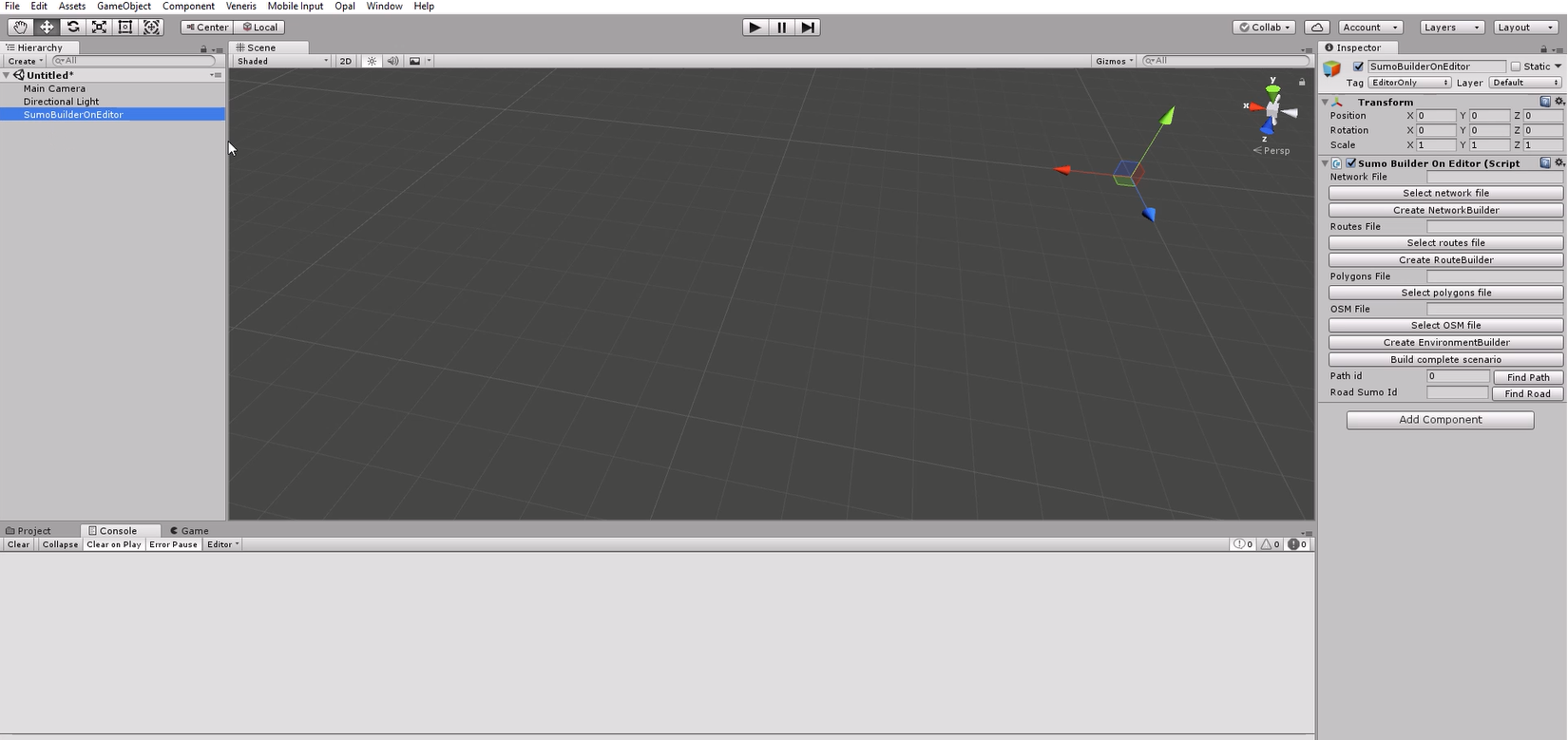
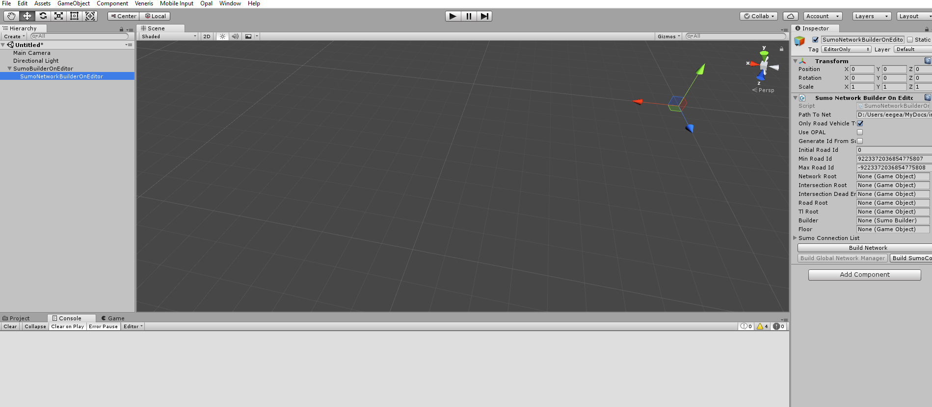
- Then click first on CreateNetworkBuilder. Now you have a child component, where you can select additional options.
-
Once you have finished setting the additional options in the child component, click Build Network and you will have the road network created.
After creating the road network, do not forget to click on BuildSumoConnections and Build Global Network Manager buttons. They are necessary to build correctly the routes.
- Do the same and create builders and build routes and environments with the other builders. Configure additional options in the child components and click on create. In particular, if you plan to use Opal late, make sure you configure the environment builder to use Opal. In the end you will have all the components you see in the last picture. At this point your scenario is generated and you can go on and add simulation components.
-
A last required step is to select the vehicle you are going to use. In the
SumoVehicleManagercomponent, set the vehicle prefab toSTDRSCar. That is the only vehicle prefab that should work correctly at the moment. Set also the Vehicle Prefab Name to "STDRSCar" if you want to use different visuals.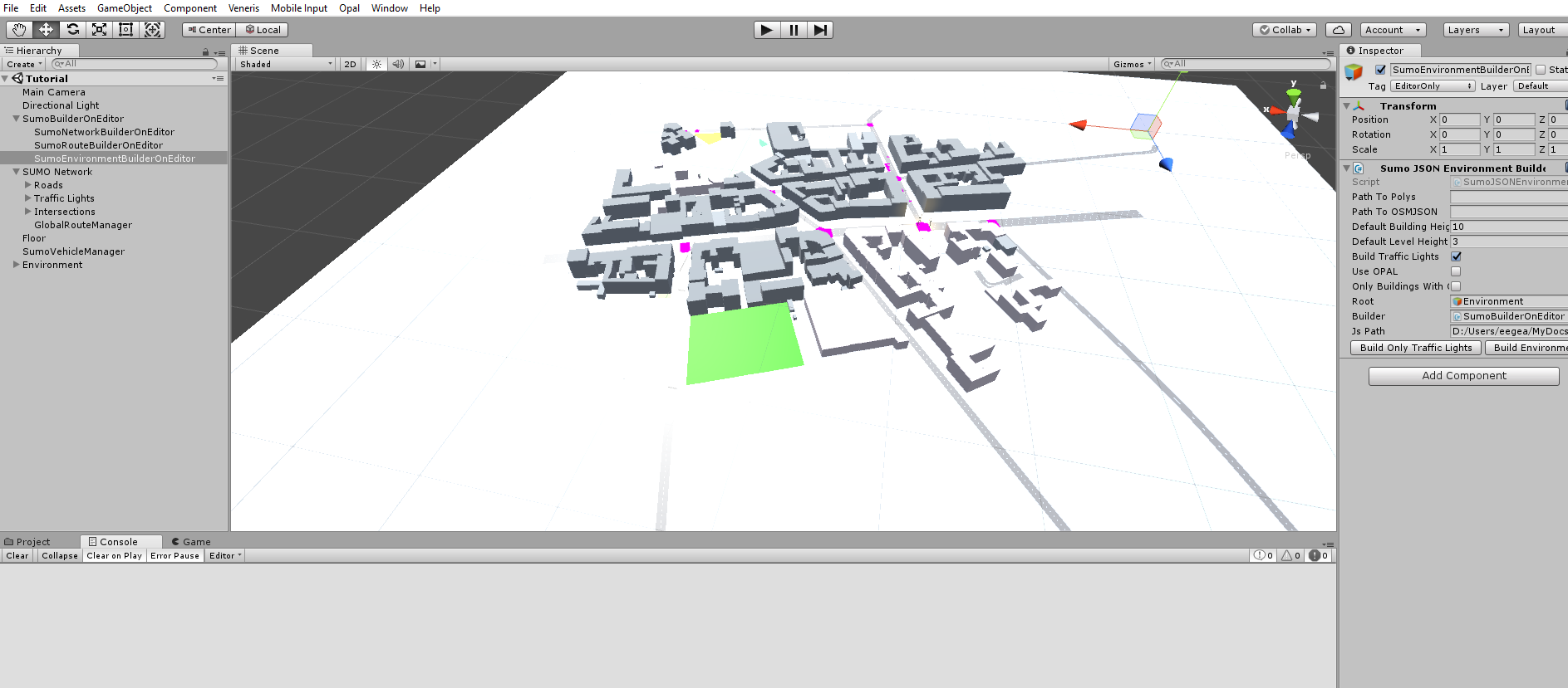
Add additional simulation components
Before starting the simulation you need to add a few more components to your scene. They are Prefabs, so you only have to drag them to your scene tree, that is, drag them from the folder to the Hierarchy tab, on the left, not the Scene tab.
-
In the Project tab, go to Resources>Prefabs in the Assets tree and drag the following prefabs to your scene (remember, drag to the Hierarchy tab):
OrbitPanZoomCamera,FollowVehicleCameraRig, this would add a couple of cameras. Delete the defaultMainCamera.Add the
SimInformationCanvasprefab that would add a UI layer to the game. You need also toCreate > UI > EventSystemfor the UI to work.Finally add a
SimulationManagerprefab.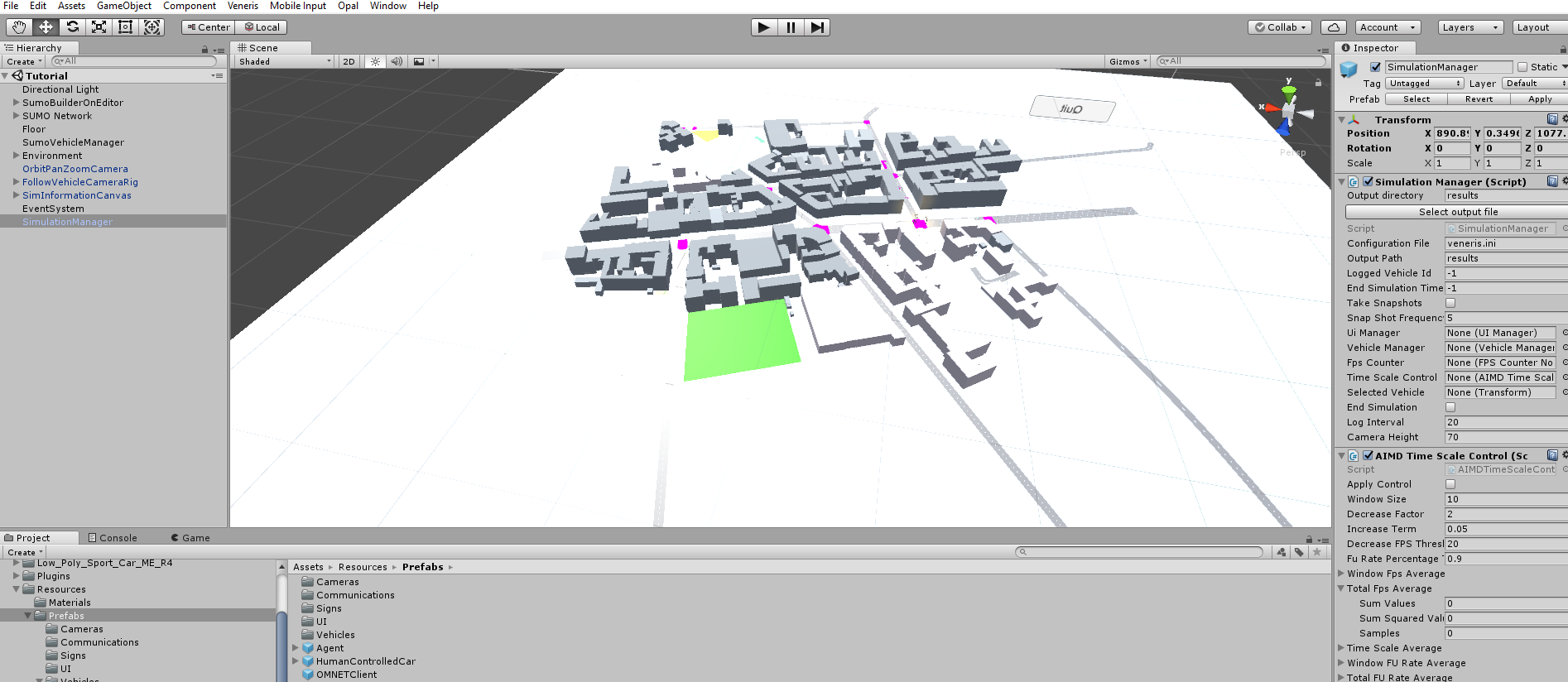
-
You need to add a configuration file to your Unity project root folder. This is a simple text file. Name this
veneris.inior whatever, but change the corresponding path and name in the SimulationManager component. In this file add the following lines:sim-time=-1 no-vehicle-manager=false output-dir=yourpath
- That's all. Now you can run your simulation on the editor or build an executable.
-
An additional tip. If you try to run a large simulation (large number of vehicles), do not use the editor (try and you'll know why). Build an executable and
run it without graphics (because you are interested in the simulation results and you do not need graphics, do you?) with
./executableName -nographics -batchmode
Hybrid simulation (unidirectional)
Build scenario
Follow the previous tutorial
Add communications components
-
Now, you need to add the components that create the messages between Veneris and OMNET++. Just drag the following prefabs
VenerisOpalManagerandExternalSimto your scene. VenerisOpalManager allows you to set Opal parameters. If you do not want to use Opal, just keep the defaults. In any case, you can override some parameters with OMNET++ and even force not to use Opal. In ExternalSim you can set the IP and port of the server or check to serialize messages to a file that can be used later with OMNET++ (unidirectional). This latter option is the preferred way at the moment. It creates a.mesfile that can be used by OMNET++ to replay your scenario. Please note that the Unity simulations are not deterministic, due to a number of reasons, in particular due to the physics engine. It means that if you want to replicate exactly the same traffic simulation but with different parameters, say different propagation models, you need to use the same .mes file. Otherwise, if you just run the same scenario with Veneris, you end up not using exactly the same traffic simulation results with OMNET++. -
Change the vehicle prefab. You have to set in the SumoVehicleManager component the vehicle prefab to
STDRSVenerisCar. Set also the vehicle prefab name to "STDRSVenerisCar" is you want to use different visuals.
Run the network simulation
-
Feed the results to OMNET++. If you decide to run a coupled simulation, you have to run the OMNET++ components (see the corresponding tutorial (coming soon) and play to set the server to listen for
Veneris messages before playing the Veneris simulation.
Otherwise, just set the path of your .mes in the
omnetpp.iniand run the OMNET++ simulator.
Electromagnetic characterization with Opal and Veneris (To be used with Veneris 0.2)
Example
You can find an example scene in the Scenes/Validation/Opal/StreetCrossingTestUpdated
Build scenario
Follow the previous tutorial if you want to build an scenario from a OSM map. You can also create your own meshes, with cubes or planes, or whatever, using Unity Create 3D Object.
Add static meshes and electromagnetic properties
For all the meshes that you want to send to Opal to participate in the ray tracing you have to add a StaticMesh component and a OpalMeshProperties component. The former does not need anything,
but for the latter you have to fill the electromagnetic values of the material. It follows the ITU-R P.2040-1 format and conventions.
If, in addition, you are going to use diffraction with edges, the faceIds have to be filled. It can be done automatically in the Opal > ExtractFaces menu.
Please. note that all of this is filled automatically if you build the scenario from OSM maps as described in the previous tutorials
Add diffracting edges
So far, only a single diffraction is implemented in the Opal simulation, which means that no high order reflections-diffractions are computed. If you want to use diffraction, you have to add the diffracting edges you want to consider.
You have to add a OpalEdge component and fill the values with the origin (O), edge vector (v), vectors describing face a (A) and face b (B) and the corresponding normals, as well as the faceId the correspond to.
Due to the involved work, you usually create a Unity script to fill these values.
Please. note that all of this is filled automatically if you build the scenario from OSM maps as described in the previous tutorials
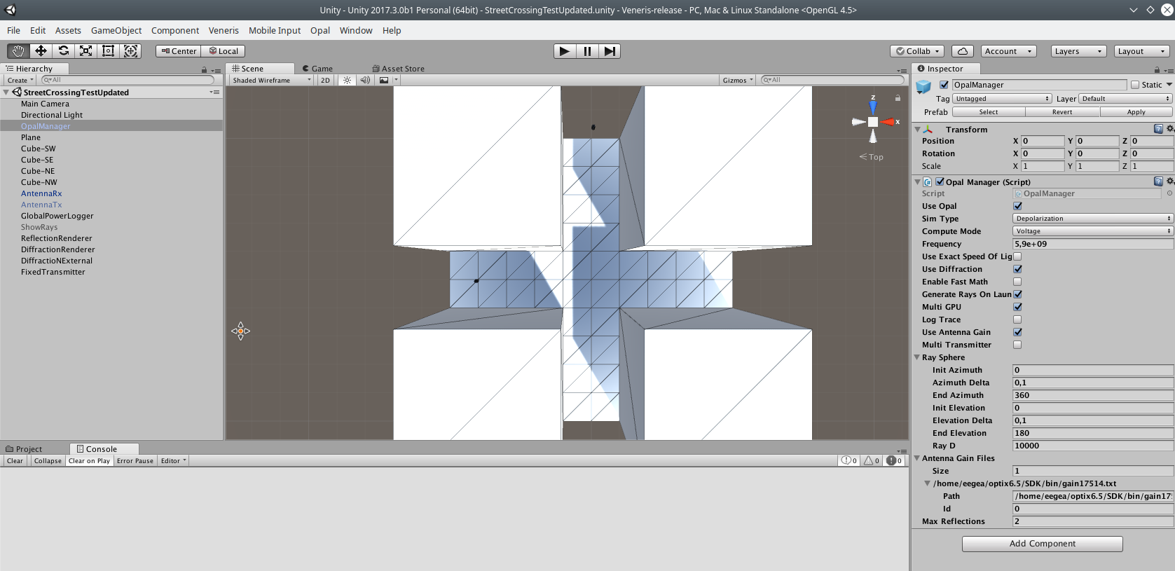
Add Opal Manager
-
Now, you have to add an Opal Manager. If you are not going to work with Veneris, you have to add just the
OpalManagercomponent. With that component you can customize the simulation optios, such as selecting the type of simulation you want to use:- Basic: only flat surfaces and horizontal or vertical polarizations.
- Depolarization: flat surfaces with any linear polarization.
- RDN: Ray Density Normalization: required for curved surfaces but can be used also with only flat surfaces. Valid for any linear polarization.
- Single diffraction: just perform diffraction simulation, no reflections. Note that you can use diffraction with all the other simulations by checking the option in OpalManager. This is for testing only diffraction
- Voltage: induced voltage on the antenna after computing depolarization and antenna gain.
- Field: electric field components on axis. This is the projection on the axis (X,Y,Z) of the electric field at the receiver point (no depolarization or antenna gain).
Add transmitter and receivers
-
Transmitters and receivers are added by creating an empty object and adding the
Antennacomponent. There are a few prefabs that can be used underResources/Prefabs/Communications. You can place multiple transmitters and checkUse Multitransmitterin the OpalManager to compute all the transmissions in parallel. It usually gives a little bit more of performance but it is usually simpler to just use a transmitter and several receivers. In general, you have to provide the code for your transmitter, or, if you just want one transmission, you can callTransmit()in theStart()method of your transmitter. Receivers may be placed by hand or with by creating an appropriate script. Make sure that you change the id of all transmitters and receivers. Every different antenna must have a different id. Antenna gain Antenna gains are provided in files with azimuth x elevation antenna gain values in dB. All the gains used have to be provided toOpalManager. Then each receiver and transmitter have to select one of the gain files (among the ones provided to OpalManager) and fill the corresponding path.
Loggers
You can add power loggers to save received power to a file by adding an empty object with a GlobalPowerLogger script and you can show the rays after transmission with the OpalLogTraceManager component. Be aware that using log traces with a very high number of rays may hang the Unity editor. You may have millions of ray hits (specially if you use RDN).
When you use a log trace manager you have to select the asset for the RayPrefab as RayRenderer in Assets (at selection) and you have to select the gameobject that is transmitting in Transmitter, which is just the origin
for the rays that are shown. The E file path is only filled if you use an external trace file.
So far the ray trace log is quite basic. For reflections, it just logs the ray hit points, sorted by number of reflections. For diffractions it is sorted by receiver, transmitter and edge. So there is no filtering by transmitter or
any other fancy function. Even though the trace records multiple transmitters (if present), the GlobalPowerLogger component only takes one transmitter, so it is better to record traces with only one transmitter (and any
number of receivers, of course).